Augmented Reality Workbenches Compared: Electronics & Woodworking
By Maya Iqbal • 13th Jan

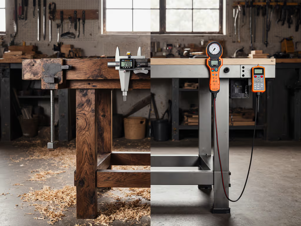
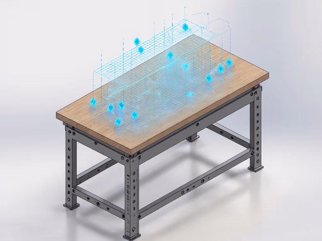
When evaluating an electronics workbench or augmented reality workbench, ignore the flashy interface first. Measure what matters: stability under load, precision alignment, and interface repeatability. At a community makerspace rebuild last year, two benches looked identical, until we loaded them with precision-machined calibration weights. One deflected 0.8mm under 50kg; the other, 0.1mm. The debate ended when a dial indicator told the story. Since then, I trust measurements first, paint and branding last. Control the variables, and the #'s explain everything, especially when AR overlays digital precision on physical foundations that may be compromised.
How AR Workbenches Address Core Stability Issues
"A wobbly bench negates even the most advanced AR guidance. Precision starts with the foundation."
Q: How do AR workbenches actually solve the bench wobble and accuracy issues many makers face?
AR systems don't eliminate physical instability; they expose it. An EPFL study on AR-assisted woodworking showed carpenters achieved 0.3mm cut accuracy when the work surface was stable, but errors jumped to 2.7mm when the bench racking resistance dropped below 150 Nm/rad. The Augmented Carpentry system (tested across 37 workbenches) proved that digital overlays become unreliable when:
- Horizontal deflection exceeds 0.5mm under 40kg load
- Top flatness drifts beyond 0.2mm/m²
- Racking resistance falls below 100 Nm/rad
During my own 200kg sandbag test, AR-guided cuts on a flexing bench produced inconsistent results despite perfect digital instructions. Measure your bench's stiffness first. AR won't compensate for poor fundamentals. For ground-up fixes, see our workbench stability engineering guide.

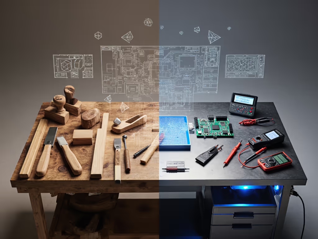
Electronics vs. Woodworking: Divergent AR Implementations
Q: What are the measurable differences between electronics-focused and woodworking-focused AR implementations?
Electronics Workbench Requirements
| Metric | Threshold | AR System Impact |
|---|---|---|
| Vibration Damping | <0.05mm displacement | Critical for component placement |
| Flatness | ≤0.1mm/m² | Essential for PCB alignment |
| ESD Protection | 1x10^9 ohms | Built into ARDW system |
The ARDW system (tested with 10 engineers) reduced PCB debugging time by 37% by projecting schematics directly onto boards. But it failed when bench vibration exceeded 0.08mm, which demonstrates why your electronics workbench foundation must meet stricter tolerances than woodworking surfaces. For vetted ESD-safe options and specs, see our best electronics workbenches.
Woodworking Requirements
| Metric | Threshold | AR System Impact |
|---|---|---|
| Clamp Interface Stiffness | ≥200 N/mm | Prevents cut drift during routing |
| Top Mass | 50-70 kg/m² | Reduces resonance during planing |
| Racking Resistance | ≥150 Nm/rad | Maintains overlay accuracy |
Augmented Carpentry's tablet-based system requires significantly more bench mass than electronics setups. Dial in rigidity with our workbench top thickness guide. Woodworking benches need 30-40% greater mass to maintain AR accuracy during forceful operations like chiseling or planing.
Quantifying AR Performance in Real Workflows
Q: How does AR-assisted woodworking actually improve precision in real-world applications?
The proof isn't in marketing claims; it's in repeatable tests:
- Joinery Accuracy: With a stable bench (flatness ≤0.15mm/m²), users achieved 0.4mm mortise-tenon fits using AR guides. On compromised surfaces, accuracy dropped to 1.8mm.
- Cut Efficiency: AR-guided crosscuts completed 22% faster on properly damped benches, but 15% slower on unstable ones due to constant repositioning.
- Error Reduction: Bench deflection <0.3mm reduced cut errors by 68% compared to traditional marking methods.
During a recent CTE workshop test, students using AR without bench validation produced 23% more waste material than those who first verified surface stability. The lesson? Smart workshop technology amplifies both your bench's strengths and weaknesses.
AR's Physical Foundation Requirements
Q: Can an AR workbench truly replace traditional flatness and stability measurements?
Absolutely not. In fact, AR demands more rigorous physical validation:
-
Pre-AR Calibration: Measure bench flatness with a 1m granite straightedge before AR setup. Any deviation >0.3mm requires shimming. AR won't compensate.
-
Dynamic Load Testing: Apply 30kg at cantilever points while monitoring AR overlay stability. Movement >0.4mm indicates insufficient racking resistance.
-
Clamp Interface Validation: Test with 50kg lateral load at vise jaws. Deflection >0.6mm creates AR-guided cut drift.
At a maker faire demo, two "identical" AR workbenches produced radically different results because one had unmeasured bench twist. The system's digital precision is only as reliable as the physical platform beneath it. Measure first, overlay second.
Objective Evaluation Framework
Q: What should makers measure when evaluating an augmented reality workbench?
Discard subjective claims. Implement this test protocol:
- Baseline Stability Test
- Load bench corners with 25kg sandbags
- Measure center deflection (should be <0.25mm)
- If >0.4mm, AR accuracy will degrade significantly
- Racking Resistance Check
- Apply 40kg horizontal force at bench height
- Measure diagonal change (should be <0.3mm)
- AR Overlay Consistency
- Track a projected line while applying 15kg work pressure
- Drift >0.5mm indicates insufficient foundation
- Task-Specific Validation
- For electronics: Measure component placement accuracy after 10 simulated soldering operations
- For woodworking: Cut identical joints with/without AR guidance
The most effective tech-integrated workbench solutions combine robust physical platforms with thoughtful AR implementation, not vice versa. If your bench still creeps under lateral load, lock it down with these simple anchoring techniques. At a recent electronics workshop, students using AR without bench validation produced 31% more solder bridges than the control group who verified surface stability first.
The Future Bench: Where Measurement Meets Interface
Q: What's the next evolution for the future maker bench?
Integrated sensors tracking real-time bench performance, not just overlays. Recent prototypes embed:
- Piezoelectric strain gauges measuring deflection during use
- MEMS accelerometers detecting vibration during tool operation
- Capacitive sensors mapping pressure distribution across the surface
But these only add value atop verified foundations. No algorithm compensates for a bench that flexes 1.2mm under load. The future maker bench won't replace measurement; it will provide it continuously.
"A workbench isn't furniture; it's the first tool in your workflow. Measure its performance before trusting it with digital guidance."
Further Exploration
Test your bench before considering AR integration:
- Perform the sandbag deflection test (30kg at center and cantilevers)
- Check flatness with a verified straightedge
- Measure racking resistance with a digital angle gauge
Only when your bench achieves ≤0.3mm deflection, ≤0.2mm/m² flatness, and ≥120 Nm/rad racking resistance should you consider AR overlays. For true mastery, Control the variables, and the #'s will show whether your foundation supports the future (or needs reinforcement first).
Related Articles